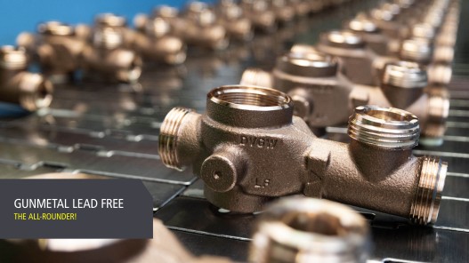
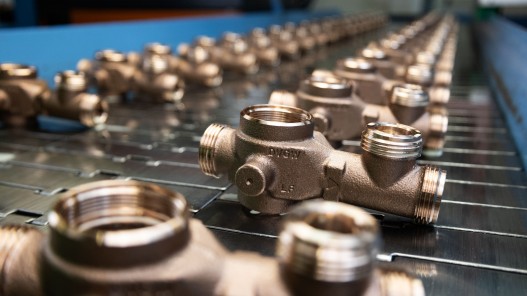
- pressure rating PN 16
- max. operating temperature 40 °C
- min. outlet pressure 0.15 MPa
- max. outlet pressure 0.7 MPa
- factory setting 0.3 MPa



Pressure reducing valve, PN 16
figure 717 0G
- internal parts made of gunmetal, stainless steel and plastic
- System protection with easy cleaning and contamination detection thanks to a transparent filter housing
Product Features
- internal parts made of gunmetal, stainless steel and plastic
- System protection with easy cleaning and contamination detection thanks to a transparent filter housing
- With stainless steel mesh at the inlet, mesh size 160 µm
- Outlet pressure adjustment scale visible from all sides
- male union thread
- for any installation position
- plugged port for optional manometer
- wetted metal parts made from dezincification-free and corrosion-resistant gunmetal, resistant against aggressive water
- maintenance requirements in accordance with DIN EN 806-5 must be complied with
- The screw fittings available as accessories are not compatible with the pressure reducing valves in pipe sizes DN 40 and DN 50.
Standards & approvals
- DVGW approval
- WRAS approval
- VA approval
- according to UBA KTW BWGL
- according to UBA BWGL Metals
- up to DN 25 soundproofing certification according to DIN EN ISO 3822 Class 1 (DN 32 Class 2)
- EN 1567
Technical data

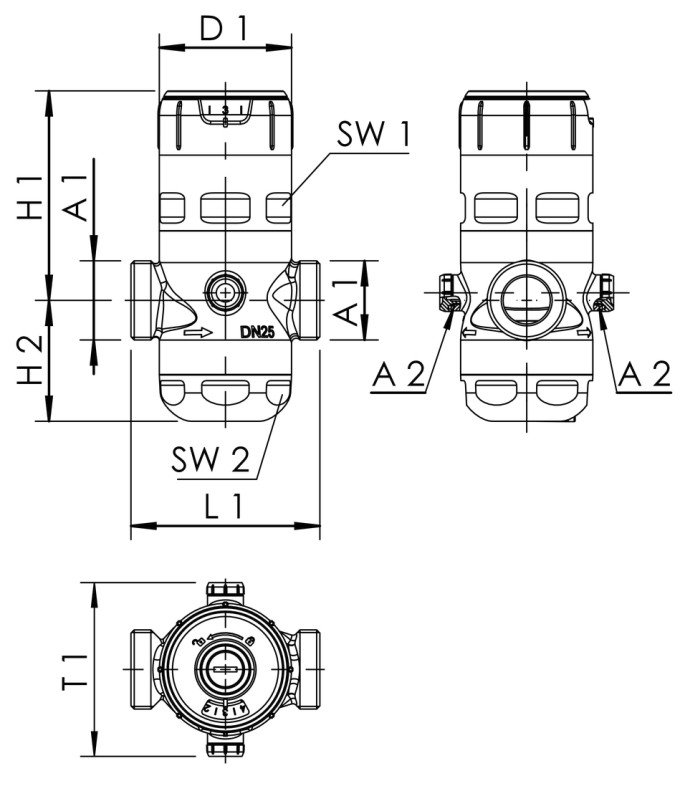
| Part no. | DN | A1 | A2 | D1 (mm) |
H1 (mm) |
H2 (mm) |
L1 (mm) |
SW1 (mm) |
SW2 (mm) |
T1 (mm) |
cv (m³/h) |
Weight (kg) |
|---|---|---|---|---|---|---|---|---|---|---|---|---|
| 7170G01500 | 15 | G 3/4 | G 1/4 | 52 | 89 | 58 | 80 | 46 | 46 | 74 | 3.4 | 0.70 |
| 7170G02000 | 20 | G 1 | G 1/4 | 52 | 89 | 58 | 90 | 46 | 46 | 74 | 4.4 | 0.74 |
| 7170G02500 | 25 | G 1 1/4 | G 1/4 | 70 | 111 | 64 | 100 | 65 | 65 | 92 | 9.3 | 1.45 |
| 7170G03200 | 32 | G 1 1/2 | G 1/4 | 70 | 111 | 64 | 105 | 65 | 65 | 92 | 10.5 | 1.48 |
| 7170G04000 | 40 | G 2 | G 1/4 | 82 | 151 | 94 | 130 | 75 | 75 | 100 | 19.5 | 2.77 |
| 7170G05000 | 50 | G 2 1/2 | G 1/4 | 82 | 151 | 94 | 140 | 75 | 75 | 100 | 20.5 | 3.14 |
Planning data
Product Guide
Here you will find, amongst other things, safety information, technical product data, information on installation and commissioning, standards and approvals, as well as accessories. You can download all the data stored for each product in a single PDF file.


